

|
|
|
|
|
|
|
|
|
|
|
|
|

| Model | Phase | Voltage | Current Output (A) | Power (KW) | Power (HP) | NEMA 4 |
|---|---|---|---|---|---|---|
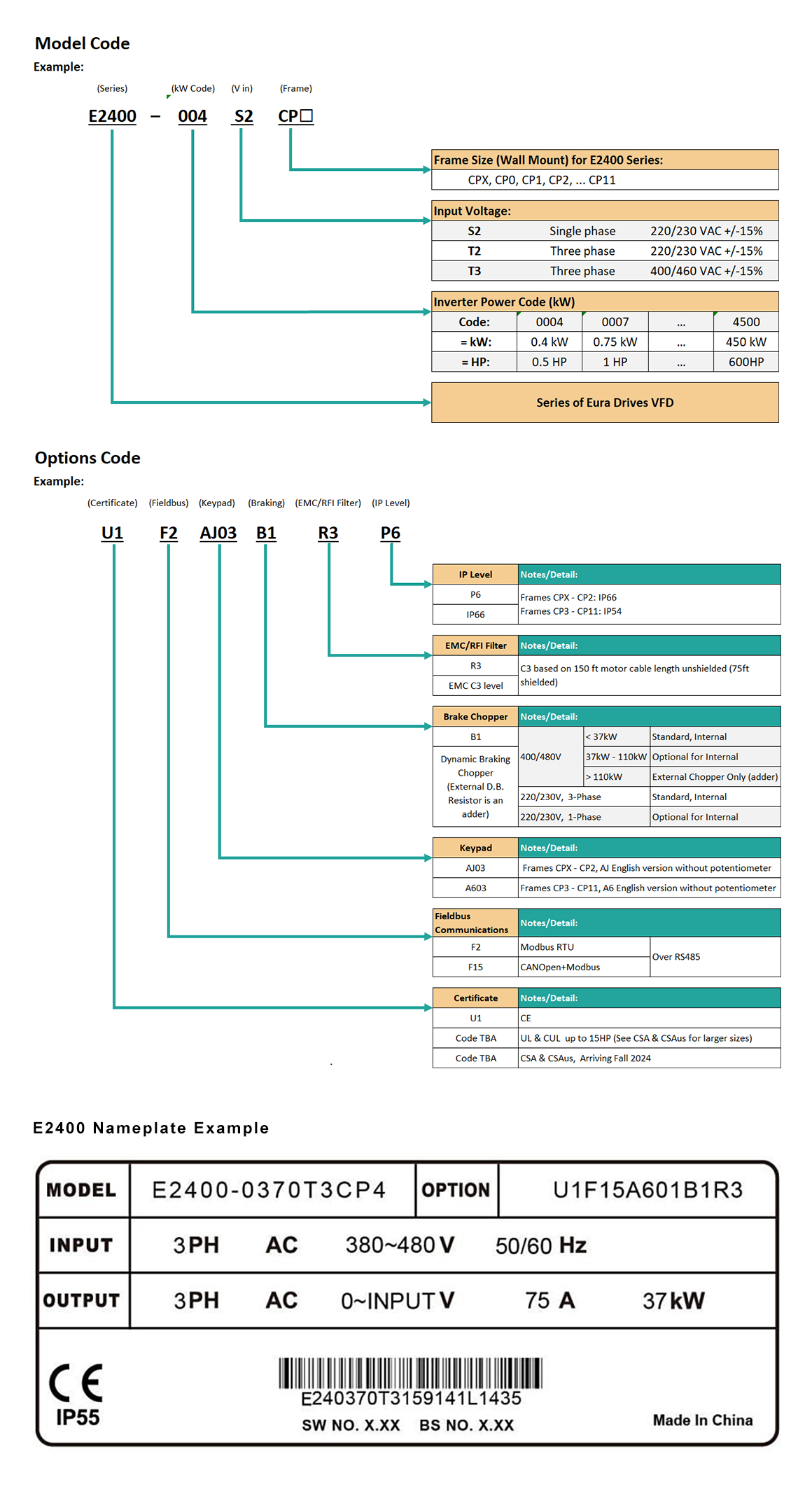
| E2400-0004S2CPX | 1 in 3 out | 230V | 2.5 | 0.4 | 0.5 | IP55 |
| E2400-0007S2CPX | 1 in 3 out | 230V | 4.5 | 0.75 | 1 | IP55 |
| E2400-0015S2CPX | 1 in 3 out | 230V | 7 | 1.5 | 2 | IP55 |
| E2400-0022S2CP0 | 1 in 3 out | 230V | 10 | 2.2 | 3 | IP55 |
| E2400-0004T2CPX | 3 in 3 out | 230V | 2.5 | 0.4 | 0.5 | IP55 |
| E2400-0007T2CPX | 3 in 3 out | 230V | 4.5 | 0.75 | 1 | IP55 |
| E2400-0015T2CPX | 3 in 3 out | 230V | 7 | 1.5 | 2 | IP55 |
| E2400-0022T2CP0 | 3 in 3 out | 230V | 10 | 2.2 | 3 | IP55 |
| E2400-0004T3CPX | 3 in 3 out | 480V | 1.1 | 0.4 | 0.5 | IP55 |
| E2400-0007T3CPX | 3 in 3 out | 480V | 1.8 | 0.75 | 1 | IP55 |
| E2400-0015T3CPX | 3 in 3 out | 480V | 3.7 | 1.5 | 2 | IP55 |
| E2400-0022T3CPX | 3 in 3 out | 480V | 6 | 2.2 | 3 | IP55 |
| E2400-0030T3CP0 | 3 in 3 out | 480V | 7 | 3 | 4 | IP55 |
| E2400-0040T3CP0 | 3 in 3 out | 480V | 8.3 | 4 | 5.5 | IP55 |
| E2400-0055T3CP1 | 3 in 3 out | 480V | 11 | 5.5 | 7.5 | IP55 |
| E2400-0075T3CP1 | 3 in 3 out | 480V | 16 | 7.5 | 10 | IP55 |
| E2400-0110T3CP2 | 3 in 3 out | 480V | 21 | 11 | 15 | IP55 |
| E2400-0150T3CP2 | 3 in 3 out | 480V | 29 | 15 | 20 | IP55 |
| E2400-0185T3CP3 | 3 in 3 out | 480V | 35 | 18.5 | 25 | IP55 |
| E2400-0220T3CP3 | 3 in 3 out | 480V | 22 | 30 | 0.5 | IP55 |
| E2400-0300T3CP3 | 3 in 3 out | 480V | 55 | 30 | 40 | IP55 |
| E2400-0370T3CP4 | 3 in 3 out | 480V | 69 | 37 | 50 | IP55 |
| E2400-0450T3CP4 | 3 in 3 out | 480V | 83 | 45 | 60 | IP55 |
| E2400-0550T3CP5 | 3 in 3 out | 480V | 101 | 55 | 75 | IP55 |
| E2400-0750T3CP5 | 3 in 3 out | 480V | 138 | 75 | 100 | IP55 |
| E2400-0900T3CP6 | 3 in 3 out | 480V | 165 | 90 | 120 | IP55 |
| E2400-1100T3CP6 | 3 in 3 out | 480V | 202 | 110 | 150 | IP55 |
| E2400-1320T3CP6 | 3 in 3 out | 480V | 243 | 132 | 175 | IP55 |
| E2400-1600T3CP7 | 3 in 3 out | 480V | 293 | 160 | 215 | IP55 |
| E2400-1850T3CP7 | 3 in 3 out | 480V | 330 | 185 | 248 | IP55 |
| E2400-2000T3CP8 | 3 in 3 out | 480V | 367 | 200 | 268 | IP55 |
| E2400-2200T3CP8 | 3 in 3 out | 480V | 403 | 220 | 295 | IP55 |
| E2400-2500T3CP9 | 3 in 3 out | 480V | 440 | 250 | 335 | IP55 |
| E2400-2800T3CP9 | 3 in 3 out | 480V | 486 | 280 | 375 | IP55 |
| E2400-3150T3CP10 | 3 in 3 out | 480V | 532 | 315 | 422 | IP55 |
| E2400-3550T3CP10 | 3 in 3 out | 480V | 587 | 355 | 476 | IP55 |
| E2400-4000T3CP11 | 3 in 3 out | 480V | 633 | 400 | 536 | IP55 |
| E2400-4500T3CP11 | 3 in 3 out | 480V | 750 | 450 | 585 | IP55 |

| Power | Ratings | 0.4~450kW (0.5 to 600HP) |
|---|---|---|
| Input V | Voltage |
3-phase 380-480V (+10%, -15%) note 1 3-phase 220V~240V ±15% 1-phase 220-240V ±15% |
| Frequency | 50/60Hz | |
| Output V | Voltage Range | 3-phase 0-INPUT (V) |
| Frequency Range | 0.50~590.0Hz (In SVC control mode, the max frequency should be lower than 500Hz.) | |
| Control Mode | Carrier Frequency | 800~16000Hz; Fixed Carrier-Wave and Random Carrier-Wave can be selected by F159. |
| Input Frequency Resolution |
Digital setting: 0.01Hz Analog setting: max frequency X 0.1% |
|
| Modes |
For Induction Motor: Closed Loop & 4-Quadrant (Closed-Loop Vector) SVC/FOC (Open-Loop Vector) For PM motor: Surface & Internal Magnets (Open/Closed Loop) For Synchronous Reluctance Motor: (Software Option, Open/Closed) |
|
| Starting Torque Boost | 0.5 Hz / 150% (SVC), 0Hz/180% (VC),5% of rated speed/100% of rated torque (PMSM SVC) | |
| Speed-control Scope | 1:100 (SVC), 1:1000 (VC), 1:20 (in PMSM SVC) | |
| Steady Speed Precision | ±0.5%(SVC), ±0.02%(VC) | |
| Torque Control Precision | ±5% | |
| Overload Capacity | 150% rated current, 60 seconds. | |
| Torque Compensation |
Auto Torque Compensation User Defined Torque Compensation includes 1-20 curves. |
|
| V/F Curve |
3 kinds of modes: Constant / Linear Variable / Squared and under-defined V/F curve |
|
| Startup modes |
Directed Rotation Startup Flying startup (V/F control) (Also stops wrong direction with DC Braking) |
|
| DC Injection Braking |
DC braking frequency: 0.20-50.00 Hz braking time: 0.00~30.00s |
|
| Jog Control | Jogging frequency range: min frequency~ max frequency, jogging acceleration/deceleration time: 0.1~3000s | |
| Auto Circulating Run Assignments |
Automatically Cycling Through: ·Lead Pump Selection (Runtime-Sharing) ·Up To 15-Stage Multi-Speeds Staging Roles |
|
| PID Controller | Easy closed-loop process control for Flow, Pressure, Temperature, Sleep Mode, Etc. | |
| Auto voltage regulation (AVR) | When source voltage changes, the modulation rate can be adjusted automatically, so that the output voltage is unchanged. | |
| Operation Function | Speed Reference(s) |
Selectable Combinations or Single Reference for Speed Via: ·Potentiometer ·External Analog Signal (0~5V, 0~10V, 0~20ma) ·Keypad (Terminal)▲/▼ Keys ·External Control Logic Auto Circulating Run Assignments |
| Start/Stop Control Source |
Selectable Combinations or Single Reference for Start/Stop Via: ·D.I. Control Terminals ·Keypad Control Fieldbus Communication Control |
|
| Frequency Reference Sources | Frequency sources can be combined: given digit, given analog voltage, given analog current and given MODBUS | |
| Accessorial frequency Sources |
7 kinds of accessorial frequency refer to F207 |
|
| Optional | Built-in EMI filter, built-in braking unit (when not included as standard), Keypad with Potentiometer, Relay & I/O expansion cards, Fieldbus cards, and more. | |
| Protection Function | Input phase loss, Output phase loss, input under-voltage, DC over-voltage, over-current, inverter over-load, motor over-load, current stall, drive over-heat, under-load, pressure control, analog line disconnected, PG line disconnection, keypad disconnection, STO and STO1. | |
| Display |
Keypad can display: output frequency, speed (rpm), output current, output voltage, linear-velocity, fault type, System & Operation parameters. LED indication: RUN = Operating Status, FWD = Forward direction is active, DGT = programming digits are selectable, FRQ = Frequency is display on screen. Input phase loss, Output phase loss, input under-voltage, DC over-voltage, over-current, inverter over-load, motor over-load, current stall, drive over-heat, under-load, pressure control, analog line disconnected, PG line disconnection, keypad disconnection, STO and STO1. |
|
| Environment Conditions | For Indoor, Harsh Locations. NEMA 4X applies up to 40HP/30kW is Corrosion Resistant & Washdown Duty; NEMA 12 applies for 50HP (37kW) and above for Heavy Dust and dripping inert liquids. Input phase loss, Output phase loss, input under-voltage, DC over-voltage, over-current, inverter over-load, motor over-load, current stall, drive over-heat, under-load, pressure control, analog line disconnected, PG line disconnection, keypad disconnection, STO and STO1. | |
| Ambient Temperature |
For Operation: -10℃ to +40℃ For Storage: -40°C to +70℃ For Handling: -20°C to +40℃ |
|
| Humidity | Below 90% (not submersible/submergible) | |
| Vibration Strength |
Frame CPX to CP2: 2g Frame CP3 to CP11: Below 0.6g (acceleration) |
|
| Elevation | Up to 1000m A.S.L. | |
| Ingress Protection level |
IP66 from 0.4kw to 30kW IP55 >30kW |
|
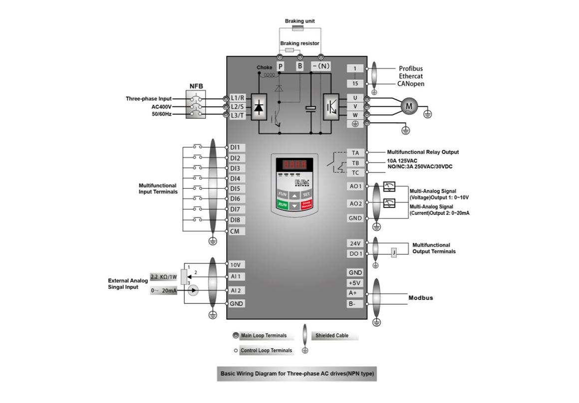
| Terminal | Type | Description | Function | |
|---|---|---|---|---|
| DO1 | Output signal | Multifunctional output terminal 1 | When the selected function is valid, the value between this terminal and CM is 0V; when the inverter is stopped, the value is 24V. Caution: Do not connect to an interposing relay when DO1 is set as high-frequency output terminal (value selection 40 = max output frequency is 100KHz). | The functions of the programmable output terminals have a manufacturer’s default value. Please reference Parameters F301 & F302 in the manual. |
| DO2Note 1 | Multifunctional output terminal 2 | When the selected function is valid, the value between this terminal and CM is 0V; when the inverter is stopped, the value is 24V. | ||
| TA | Relay contact | When the selected function is valid, the value between this terminal and CM is 0V; when the inverter is stopped, the value is 24V. | ||
| TB | ||||
| TC | ||||
| AO1 | Voltage/current output | Analog output AO1 can be connected to either a frequency meter, speedometer or ammeter externally; The negative of the meter would then be connected with VFD Control Terminal GND. See F423~F426 for details. Analog Output can also be used as speed reference for a slave VFD. | ||
| AO2 | Current output | Analog output AO2 can be connected with ammeter externally, the negative of the meter would then be connected with VFD Control Terminal GND. See F427~F430 for details. Analog Output can also be used as speed reference for a slave VFD. | ||
| 10V | Analog power supply | VFD internal power supply | Analog output AO1 can be connected to either a frequency meter, speedometer or ammeter externally; The negative of the meter would then be connected with VFD Control Terminal GND. See F423~F426 for details. Analog Output can also be used as speed reference for a slave VFD. | |
| AI1 Note 2 | Analog Input Signal | Voltage input Terminal. Default setting of AI1 is 0~10V |
When analog speed control is adopted, the external instrument voltage or current signal is input through this terminal. The range of voltage input is 0~5V or 0~10V or -10V-10V; current input is 0~20mA; input resistance is 50 Ohms, and grounding: GND
If the input is 4~20mA, it can be realized by setting F406=2. The voltage or current signal can be chosen by the coding switch on the control board. See table 5-2, 5-3 for details, and F438 and F439 also should be set accordingly. |
|
| AI2 |
Voltage / Current input Terminal. Default setting of AI2 is 0~20mA. |
|||
| GND |
Self-contained Power supply Ground |
Ground terminal of external control signal (voltage control signal or current source control signal) is also the ground of 10V power supply of this inverter. | ||
| 24V | Power supply | Control power supply | Power: 24±1.5V, grounding is CM; current is restricted below 200mA for external use. | |
| DI1 | Default Digital input control terminal | Jog (Forward Direction) | When this terminal is valid, the inverter will have jogging running. The jogging function of this terminal is valid under both at stopped and running status. This terminal can also be used as high-speed pulse input port. The max frequency is 100KHz. | The functions of the input terminals have factory default settings. Please reference the manual for reassigning the functions. |
| DI2 | External Fault Interlock | When this terminal is valid, “ESP” malfunction signal will be displayed. A permissive loop that generates a fault. | ||
| DI3 | “FWD” | When this terminal is valid, inverter will run forward. | ||
| DI4 | “REV” | When this terminal is valid, inverter will run in reverse. | ||
| DI5 | Reset | Resets the VFD Fault (if fault is cleared) when the terminal is valid. | ||
| DI6 | Coast To Stop | Motor Coasts to Stop when this terminal is valid. | ||
| DI7 Note 1 | Available DI Terminal | |||
| DI8 Note 1 | Stop terminal | Available DI Terminal | ||
| CM | Common | Return terminal of the control power supply | The negative terminal of the 24V power supply on the drive’s control board. | |
| GND | RS485 communication terminals | Ground | Grounding of differential signal | |
| 5V | Power Supply | 5V Power Supply of the differential signal | ||
| A+ | Positive polarity of differential signal |
Standard: TIA/EIA-485(RS-485) Communication protocol: Modbus Communication Baud Rate: 1200/2400/4800/9600/19200/38400/57600bps |
||
| B- | Negative polarity of Differential signal | |||
| GND | CAN communication | CAN cable shield | CANopen cable’s shielded layer Note 3 | |
| H | CAN Cable High |
CANopen Baud Rate: Note 2 20/50/100/125/250/500/1000kbps |
||
| L | CAN Cable Low | |||

| TA | TB | TC | DO1 | DO2 | 24V | CM | DI1 | DI2 | DI3 | DI4 | DI5 | DI6 | DI7 | DI8 | 10V | AI1 | AI2 | GND | AO1 | AO2 |
|---|---|---|---|---|---|---|---|---|---|---|---|---|---|---|---|---|---|---|---|---|
| GND | 5V | A+ | B- | GND | H | L |
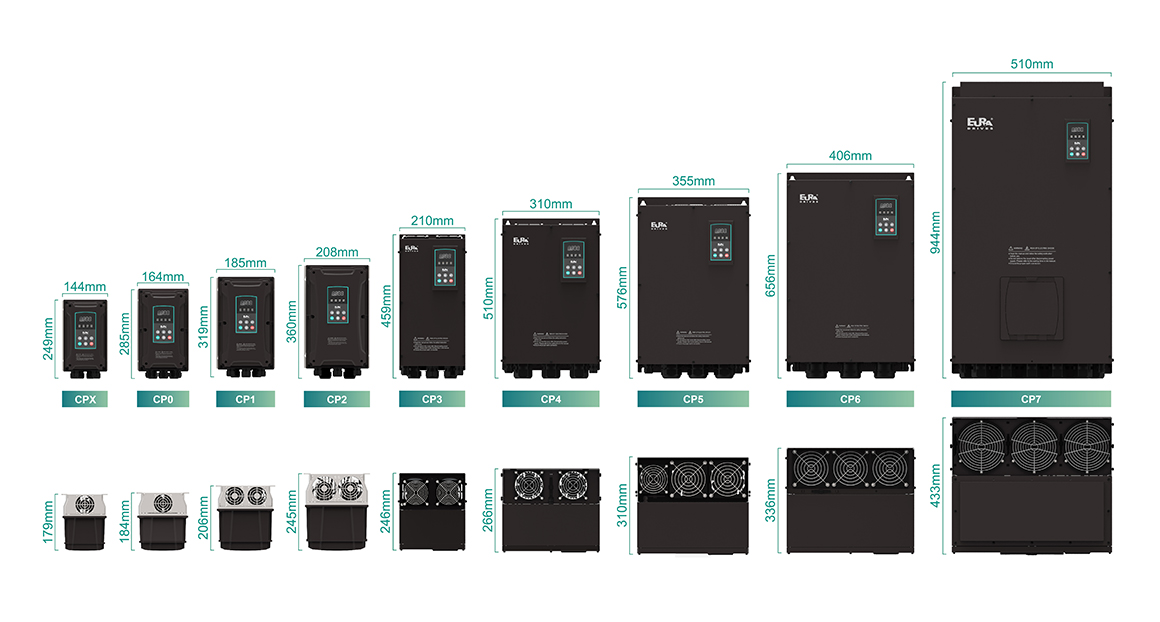
| Eura Drives E2400 Model | kW rating (150% OL) | FLA Output | Frame Size | Voltage | Heat Dissipation Note | Front Casing Design |
|---|---|---|---|---|---|---|
| E2400-0004S2 | 0.4 | 2.5 | CPX | 1Ø in 3Ø out 230V | Self-cooling | Industrial Polymer Front Casing |
| E2400-0007S2 | 0.75 | 4.5 | CPX | 1Ø in 3Ø out 230V | Fan Cooled | |
| E2400-0015S2 | 1.5 | 7.0 | CPX | 1Ø in 3Ø out 230V | Fan Cooled | |
| E2400-0022S2 | 2.2 | 10.0 | CP0 | 1Ø in 3Ø out 230V | Fan Cooled | |
| E2400-0004T2 | 0.4 | 2.5 | CPX | 230V 3Ø in 3Ø out | Fan Cooled | |
| E2400-0007T2 | 0.75 | 4.5 | CPX | 230V 3Ø in 3Ø out | Fan Cooled | |
| E2400-0015T2 | 1.5 | 7 | CPX | 230V 3Ø in 3Ø out | Fan Cooled | |
| E2400-0022T2 | 2.2 | 10.0 | CP0 | 230V 3Ø in 3Ø out | Fan Cooled | |
| E2400-0004T3 | 0.4 | 1.2 | CPX | 480V 3Ø in 3Ø out | Self-cooling | |
| E2400-0007T3 | 0.75 | 2.0 | CPX | 480V 3Ø in 3Ø out | Fan Cooled | |
| E2400-0015T3 | 1.5 | 4.0 | CPX | 480V 3Ø in 3Ø out | Fan Cooled | |
| E2400-0022T3 | 2.2 | 6.5 | CP0 | 480V 3Ø in 3Ø out | Fan Cooled | |
| E2400-0030T3 | 3.0 | 7.6 | CP0 | 480V 3Ø in 3Ø out | Fan Cooled | |
| E2400-0040T3 | 4.0 | 9.0 | CP0 | 480V 3Ø in 3Ø out | Fan Cooled | |
| E2400-0055T3 | 5.5 | 12.0 | CP1 | 480V 3Ø in 3Ø out | Fan Cooled | |
| E2400-0075T3 | 7.5 | 17.0 | CP1 | 480V 3Ø in 3Ø out | Fan Cooled | |
| E2400-0110T3 | 11 | 23.0 | CP2 | 480V 3Ø in 3Ø out | Fan Cooled | |
| E2400-0150T3 | 15 | 32.0 | CP2 | 480V 3Ø in 3Ø out | Fan Cooled | |
| E2400-0185T3 | 18.5 | 38 | CP3 | 480V 3Ø in 3Ø out | Fan Cooled | Industrial Metal Front Casing |
| E2400-0220T3 | 22 | 44 | CP3 | 480V 3Ø in 3Ø out | Fan Cooled | |
| E2400-0300T3 | 30 | 60 | CP3 | 480V 3Ø in 3Ø out | Fan Cooled | |
| E2400-0370T3 | 37 | 75 | CP4 | 480V 3Ø in 3Ø out | Fan Cooled | |
| E2400-0450T3 | 45 | 90 | CP4 | 480V 3Ø in 3Ø out | Fan Cooled | |
| E2400-0550T3 | 55 | 110 | CP5 | 480V 3Ø in 3Ø out | Fan Cooled | |
| E2400-0750T3 | 75 | 150 | CP5 | 480V 3Ø in 3Ø out | Fan Cooled | |
| E2400-0900T3 | 90 | 180 | CP6 | 480V 3Ø in 3Ø out | Fan Cooled | |
| E2400-1100T3 | 110 | 220 | CP6 | 480V 3Ø in 3Ø out | Fan Cooled | |
| E2400-1320T3 | 132 | 265 | CP6 | 480V 3Ø in 3Ø out | Fan Cooled | |
| E2400-1600T3 | 160 | 320 | CP7 | 480V 3Ø in 3Ø out | Fan Cooled | |
| E2400-1850T3 | 185 | 360 | CP7 | 480V 3Ø in 3Ø out | Fan Cooled | |
| E2400-2000T3 | 200 | 400 | CP8 | 480V 3Ø in 3Ø out | Fan Cooled | |
| E2400-2200T3 | 220 | 440 | CP8 | 480V 3Ø in 3Ø out | Fan Cooled | |
| E2400-2500T3 | 250 | 480 | CP9 | 480V 3Ø in 3Ø out | Fan Cooled | |
| E2400-2800T3 | 280 | 530 | CP9 | 480V 3Ø in 3Ø out | Fan Cooled | |
| E2400-3150T3 | 315 | 580 | CP10 | 480V 3Ø in 3Ø out | Fan Cooled | |
| E2400-3550T3 | 355 | 640 | CP10 | 480V 3Ø in 3Ø out | Fan Cooled | |
| E2400-4000T3 | 400 | 690 | CP11 | 480V 3Ø in 3Ø out | Fan Cooled | |
| E2400-4500T3 | 450 | 770 | CP11 | 480V 3Ø in 3Ø out | Fan Cooled |

Note:
1. For single-phase conversion, only connect power terminals L1/R and L2/S to Main Power.
2. The RS485 communication port utilizes native MODBUS RTU communication protocol. The communication port is on the left side of the inverter.
For inverters <37KW>30KW, the sequence from top-down is GND, 5V power, A+, & B-.
3. Inverters >37KW have 8 multifunctional input terminals DI1~DI8.
For inverters <45KW>
4. The output relay contact capacity is 10A/125VAC. NO/NC: 3A 250VAC/30VDC.